Skip to content
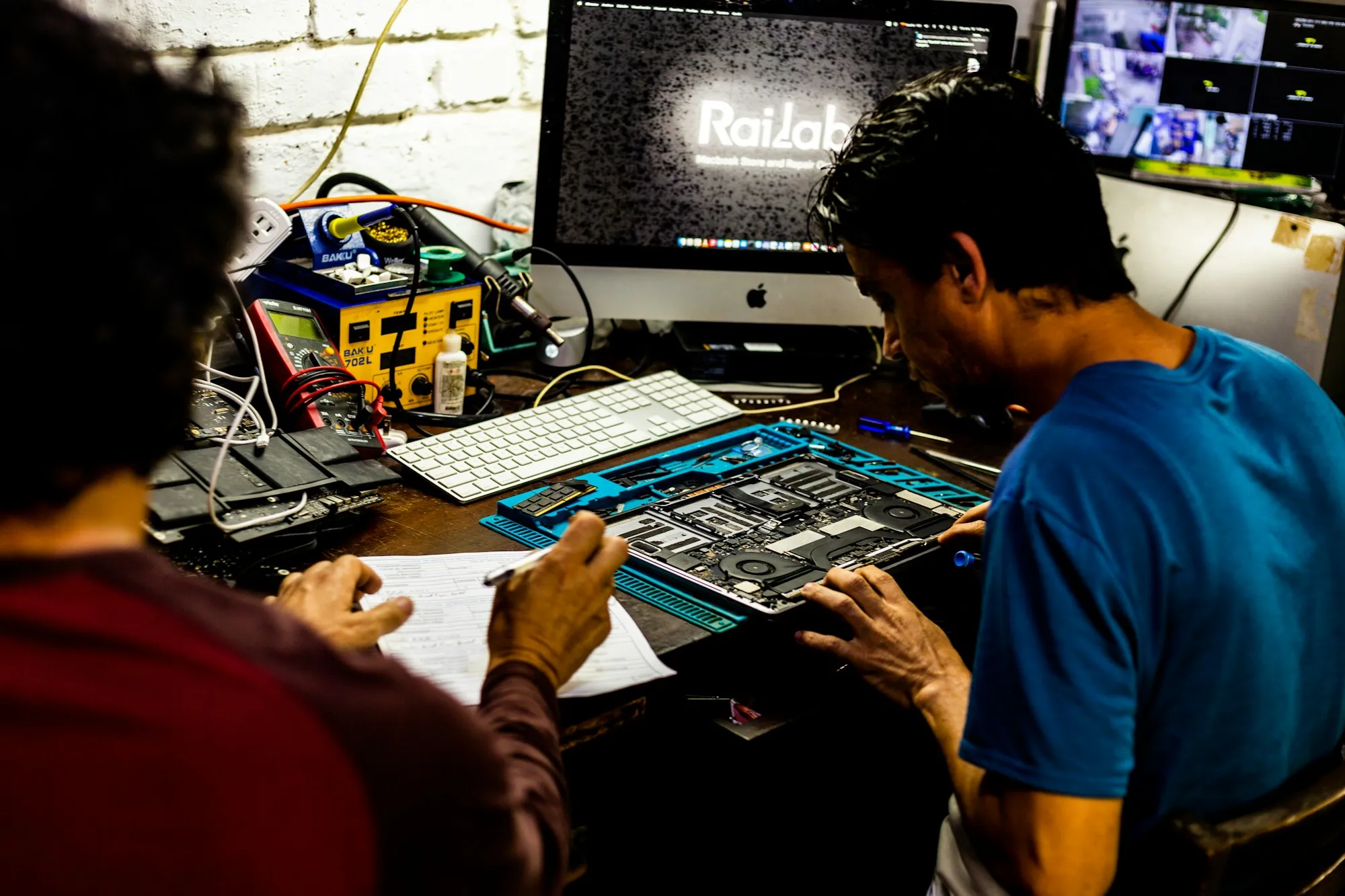
Engineers inspecting a control mainboard at a workbench

Hardware ODM development

Co-development, not just parts

We take part in requirement definition, hardware architecture, board development, prototype validation and pilot build — turning a display control approach into hardware that enters a real product, rather than a concept diagram.

Starting point
A device goal, not a finished spec
Stages
Review → architecture → board → prototype → pilot
Handover
Hardware + engineering documents

WHY ODM

Why display control hardware ODM

A display-device project is rarely a single hardware problem. The enclosure decides board size and connector direction, the module documentation decides output timing and receiving-side load, the cost target decides components and PCB approach, the installation environment decides temperature, protection and service method, and the production method decides test points, programming flow and fixture design.

Selling standard boards alone leaves projects blocked at structure, interface, harness, cost or test. Doing assembly alone leaves the customer carrying chain definition and fault location. HQControl sits between product development and production introduction, staying involved across architecture, hardware, firmware, prototype and pilot build.

SERVICE SCOPE

What we take on

Service scope from solution definition to pilot cooperation

  • Requirement definition and display-control solution review
  • FPGA / MCU control board, sending card, receiving card and interface-board development
  • Prototype debugging, signal-chain validation, display-output checks and reliability review
  • Key component selection, sourcing coordination and alternative-part suggestions
  • Pilot production, test fixture / workflow support and supply-chain cooperation
  • Interface adaptation, cost optimisation and revision work on an existing customer design

PROCESS

Six stages

Input, work and deliverables at each stage

The process moves from uncertain to defined: review the requirement, define the architecture, build the board, debug the logic, validate the prototype, then support the pilot build.

  1. 01

    Requirement Review

    Clarify display type, application scenario, screen size or resolution, refresh needs, input/output interfaces, control method, installation environment, mechanical limits, target cost, planned quantity and project stage. The aim is not an immediate quote but turning a vague requirement into engineering questions that can be judged.

    You provide
    • Display type and target resolution
    • Interface requirements
    • Enclosure constraints, cost target and volume
    Deliverables
    • Requirement brief
    • Initial risk notes
    • Architecture direction
  2. 02

    Architecture Definition

    Break the requirement into source, control core, sending/output unit, transmission link, receiving/module control, display output, power, structure, firmware and production-test boundaries — and decide what the FPGA carries, what the MCU carries, and whether separate sending, receiving or interface boards are needed.

    You provide
    • Confirmed requirements
    • Screen or module information
    • Mechanical outline and preferred interfaces
    Deliverables
    • System block diagram
    • Interface plan
    • Development scope
    • Risk register
  3. 03

    Schematic and PCB Development

    Develop schematic, PCB, key component selection, BOM, test points, interface definition and board-version management. PCB work accounts for high-speed signal integrity, power stability, thermal path, connector position, assembly, production test and later repair — designed for manufacture, not only for the lab.

    You provide
    • Architecture scope
    • Mechanical constraints
    • Target BOM and interface definition
    Deliverables
    • Schematic files
    • PCB files
    • BOM draft
    • Test-point plan
    • Board revision notes
  4. 04

    FPGA / MCU Control Logic and Debugging

    Develop and debug FPGA control logic, MCU firmware, interface communication, power-on sequence, status feedback, exception handling and the debugging workflow — locating whether an issue sits at the input, the control logic, the transmission link, the receiving side, the module, power, mechanical interference or the firmware flow.

    You provide
    • Prototype board
    • Firmware scope
    • Display module and test environment
    Deliverables
    • Debug notes
    • Firmware or logic revision
    • Issue list
    • Next-revision suggestions
  5. 05

    Prototype Validation

    Validate power-on, communication, display output, interface link, timing, sync, stability, basic aging and issue reproduction. The point is not a single demonstration but confirming the approach is ready to be revised, piloted and integrated into the customer device.

    You provide
    • Engineering samples
    • Test plan
    • Display target and acceptance expectations
    Deliverables
    • Prototype test record
    • Issue list
    • Validation summary
    • Revision plan
  6. 06

    Pilot Production and Production-Test Support

    Support component sourcing, alternative-part review, test fixtures, test workflow, acceptance criteria, batch records, packaging and supply-chain issue closure. The cooperation model, test scope and delivery boundary are confirmed per project rather than promised as a fixed lead time.

    You provide
    • Pilot quantity and BOM status
    • Test requirements
    • Factory conditions and logistics boundary
    Deliverables
    • Pilot support notes
    • Production-test workflow
    • Acceptance checklist
    • Handoff notes

DELIVERABLES

More than a prototype

Engineering documents delivered by stage

These are what let a customer team keep maintaining, producing and iterating instead of the project living in one person’s head.

  • Requirement review Requirement brief Locks down objectives, display parameters, interfaces, structure, cost, schedule and risks before development starts, in a form engineering, purchasing and management can confirm together.
  • Architecture definition Control-chain architecture note Explains the relationship between input source, control processing, sending side, receiving side, display module, MCU management, test interface and service method.
  • Board development Hardware design package Schematic, PCB, BOM, key component notes, connector definition, test points and assembly notes.
  • Control logic Firmware and logic package MCU firmware version, FPGA logic version, programming files, interface protocol, test commands and version naming rules.
  • Prototype validation Prototype bring-up report Records power-on, programming, bring-up, communication, test patterns, temperature rise, recovery and issue closure — the basis for a pre-production decision.
  • Pilot production Pilot test plan Defines line programming, display test, interface test, labelling, records and reject criteria so an engineering prototype becomes a production item.
  • Lifecycle Design change log Records the reason, scope and confirmation of hardware, firmware, BOM, structure and test-process changes so later maintenance stays traceable.

DEMO

Customer validation

A demo prototype is revision input, not a showpiece

Showroom units, demo prototypes and customer validation

Showroom units, demo prototypes and customer validation

Project context

A showroom or demo prototype is where the customer confirms display result, control method, interface layout and overall feasibility with their own team or their end client. The hardware has to work and also support stable demonstration and quick fault location.

Control hardware focus

Prototype control board, temporary debug interface, test patterns, parameter switching, demo mode and issue logging. The goal is verifying the real technical path, not building a showpiece.

How the work runs

Define what the demo has to prove — bring-up, clarity, refresh, brightness, control method, interface position, boot flow and recovery — then prepare hardware, firmware version, test patterns and a record sheet. Feedback afterwards is split into structural, hardware, firmware, display-parameter and production issues.

Validation points

  • Demo content matches the real project targets
  • Control interface, display result and recovery are reproducible
  • Feedback converts into actionable revision items
  • Prototype version, firmware version and test records are complete

COOPERATION

Three ways to start

Cooperation models and project boundaries

Display control hardware inquiry

  • company
  • display type
  • target resolution
  • interface requirements
  • estimated volume
  • schedule

ODM development cooperation

  • product stage
  • existing specs
  • required board type
  • firmware scope
  • prototype quantity
  • certification or test needs

Pilot production and testing support

  • bom status
  • test requirements
  • planned quantity
  • target factory or supply chain
  • quality requirements

Project boundary

  • Hardware control approach, board development, firmware/logic and prototype validation: developed here.
  • Panels, mechanical parts, enclosures and device certification: supplied by the customer or assessed separately.
  • Host software, cloud back-ends and content management: outside this service.
  • Production responsibility and logistics boundary: confirmed per cooperation model in contract.

Quotations follow specification, interfaces, hardware complexity, prototype quantity, BOM, validation scope and cooperation model. No fixed price or lead time is published here.

HANDOVER

From prototype to production handover

Many hardware projects stall after the prototype. An engineering sample can be hand-tuned by its developer, but a production line needs a fixed method to program, test and judge. An engineer knows about a jumper wire or a temporary setting; production staff need documents, labels and records. Purchasing can find a batch of parts once; volume needs lead time and alternatives.

Handover therefore covers the confirmed schematic, PCB, BOM, firmware, programming files, test workflow, key component notes, assembly notes, labelling rules, record templates and an issue feedback route. This is what reduces pilot-run confusion and keeps later maintenance and revisions possible.

FAQ

ODM FAQ

What should the HQControl website focus on?

Control hardware and ODM services behind advertising screens, commercial displays and custom display devices, including FPGA, MCU, sending cards, receiving cards, control units, display control modules, prototype validation and production-test cooperation.

Is HQControl a software platform or SaaS company?

No. We write firmware and control logic because control hardware needs it, and we define the command interface a customer’s own system talks to. We do not sell a cloud application, a software platform or a subscription service.

Which display control hardware can be customized?

Project work can cover FPGA control hardware, MCU control systems, sending cards, receiving cards, control units, interface boards and display control modules. Exact specifications, interfaces, size and production terms are confirmed per project.

Can the site publish performance specifications?

Only confirmed specifications are published, including resolution, refresh, interfaces, latency, power, operating temperature, certifications and production capacity. Before confirmation, capability-level wording is used.

How is the ODM process structured?

Requirement review, solution definition, schematic/PCB work, prototype build, firmware debugging, validation testing, BOM/sourcing coordination, pilot build and production support.

Do you promise fixed lead times and fixed prices?

No. Display control hardware projects depend on interfaces, board complexity, prototype quantity, validation scope and supply chain conditions. Pricing and lead time follow project review.

Project inquiry

Turn display requirements into validated, manufacturable control hardware

Share display type, target specifications, interface requirements and project stage. We review the control hardware approach and ODM cooperation model; pricing and lead time follow project review.

Helpful to include

  • Screen size, pixel pitch, module layout and target resolution
  • Input source, control distance, sending/receiving count and cabling
  • Enclosure space, connector direction, power, temperature rise and service access
  • Test patterns, long-run checks, restart recovery and the factory-test standard
  • Existing boards, BOM, schematics or fault samples, if any
  • Estimated volume, project stage and target schedule