
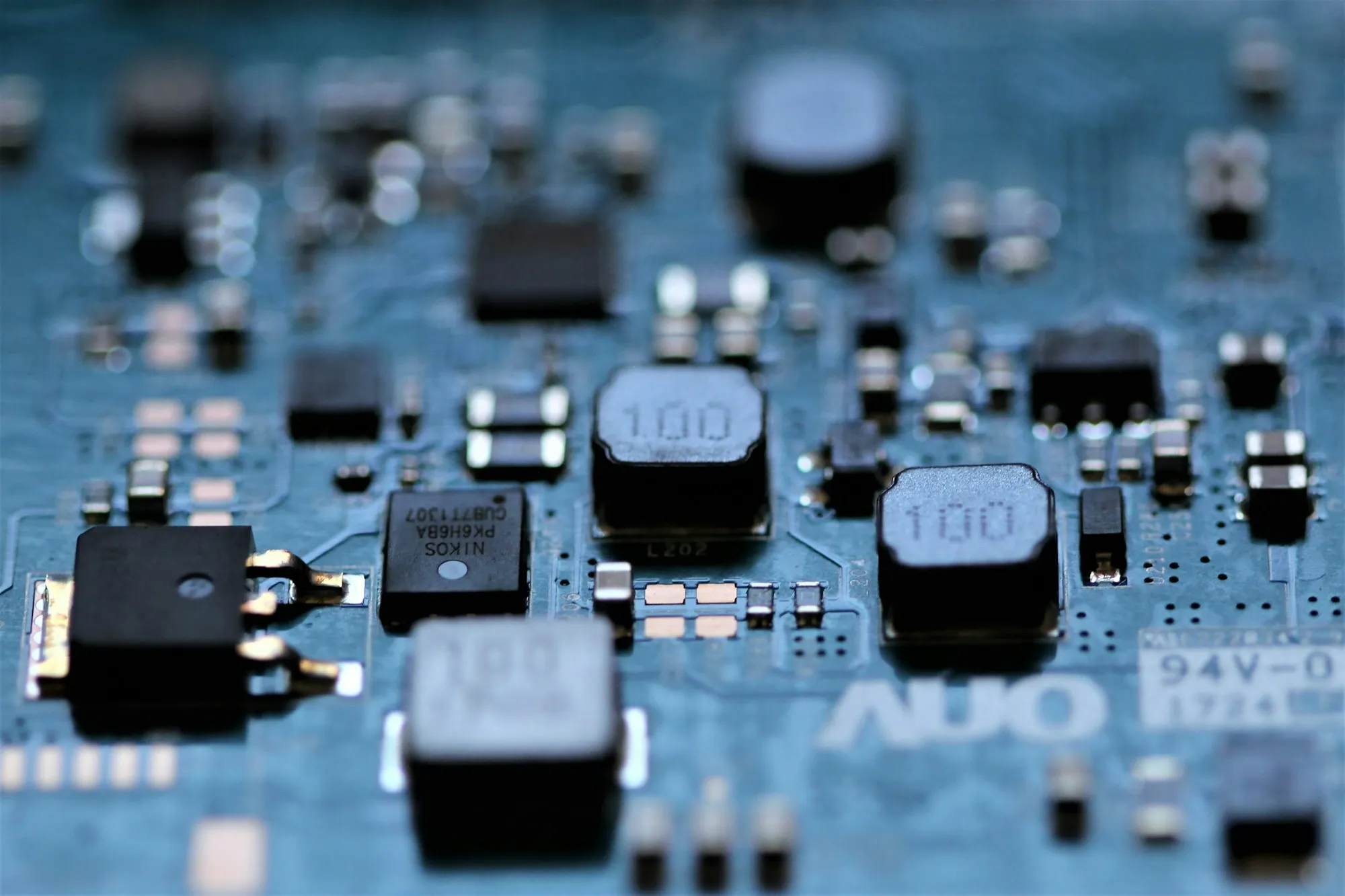
FPGA Display Control Hardware
FPGA-based control hardware for high-speed display links, pixel processing, timing control and multi-interface output.
HQControl Display Control Hardware
HQControl develops FPGA/MCU control hardware, sending cards, receiving cards, control units and interface boards for advertising screen, commercial display and custom display manufacturers — with prototype validation, production testing and supply-chain cooperation.
POSITIONING
Advertising screens, commercial displays, small display products and large LED display systems all look like “a screen”. What actually decides whether the product runs stably is the control hardware behind it.
The customer sees brightness, picture, response, stability, interfaces and appearance. The engineering team faces the signal chain, timing, bandwidth, power, thermal behaviour, structure, firmware, test and supply chain.
Control hardware does not need to be as complex or as high-spec as possible — it needs to suit the product target. A retail signage project may weight cost, stability and peripheral control; an outdoor LED project may weight the receiving side, reliability, batch consistency and service access.
WHERE TO START
Three ways in
The outer layer is the display application a customer already knows; the inner layer is FPGA, MCU, sending cards, receiving cards, interface boards and production test.
Control hardware for outdoor LED advertising, retail signage, indoor commercial display devices, public information screens and custom display products.
FPGA + MCUFPGA carries display timing, pixel mapping and interface bridging; MCU carries command packets, status readback, fault codes, programming and factory test.
Hardware ODM developmentRequirement review, architecture, schematic and PCB, FPGA/MCU control logic, prototype validation, BOM coordination and production-test support.
CONTROL CHAIN
System view
Customers usually arrive with a device goal rather than a finished specification. The work is to break it into input, control, sending, transmission, receiving, display and test boundaries.
CAPABILITIES
Hardware capability
Each capability is combined around the customer device requirement rather than sold as a fixed model.
FPGA-based control hardware for high-speed display links, pixel processing, timing control and multi-interface output.
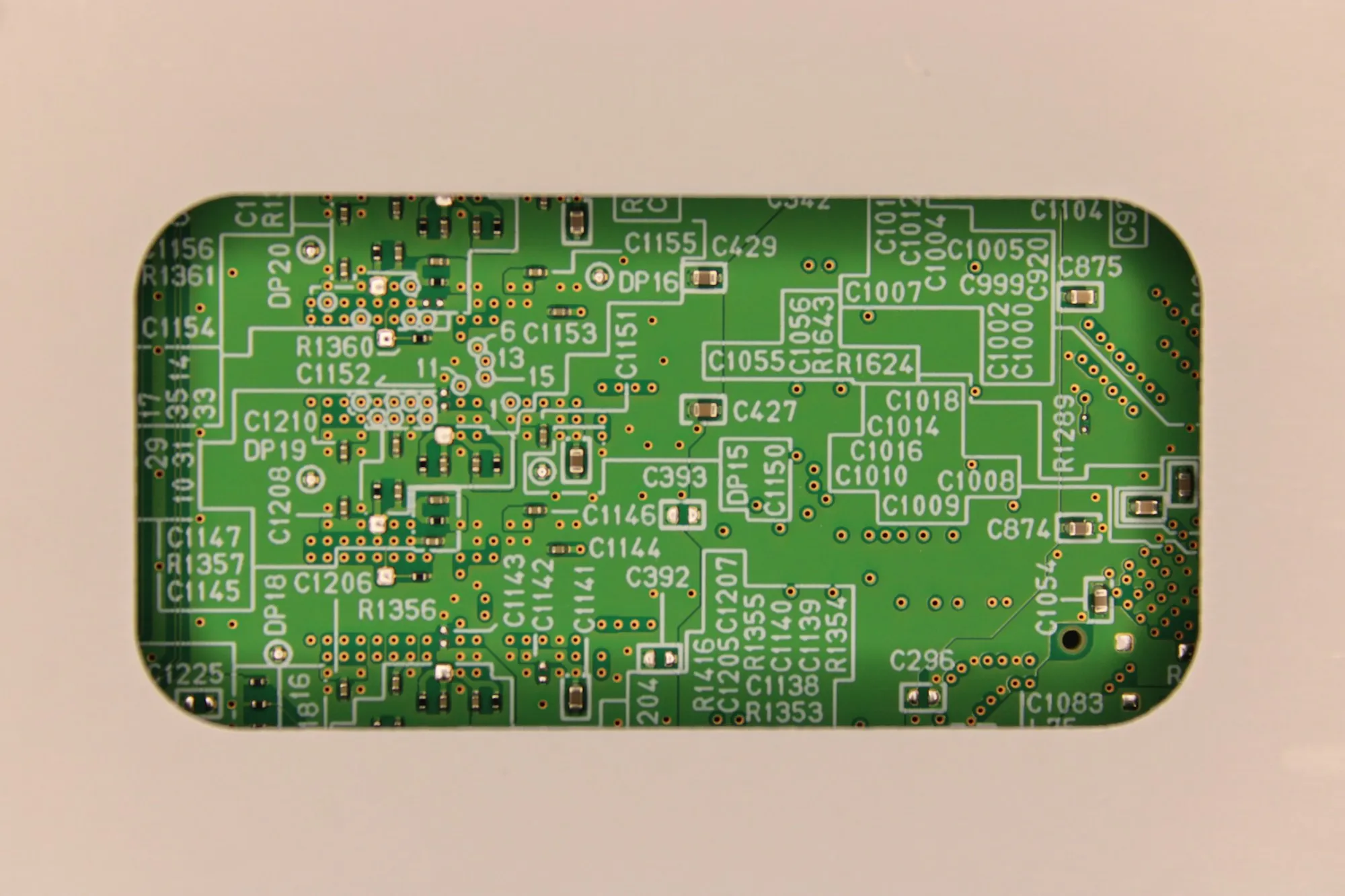
MCU control systems for display-device state control, interface management, peripheral coordination and device logic.
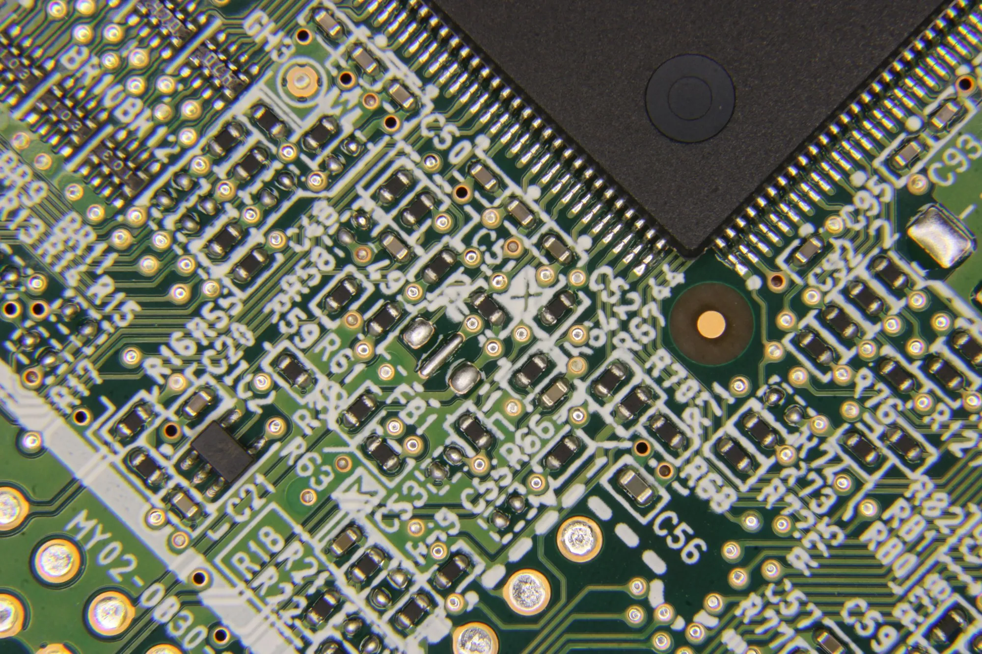
Sending-card and output-control-unit development for display signal input, processing, distribution and output.
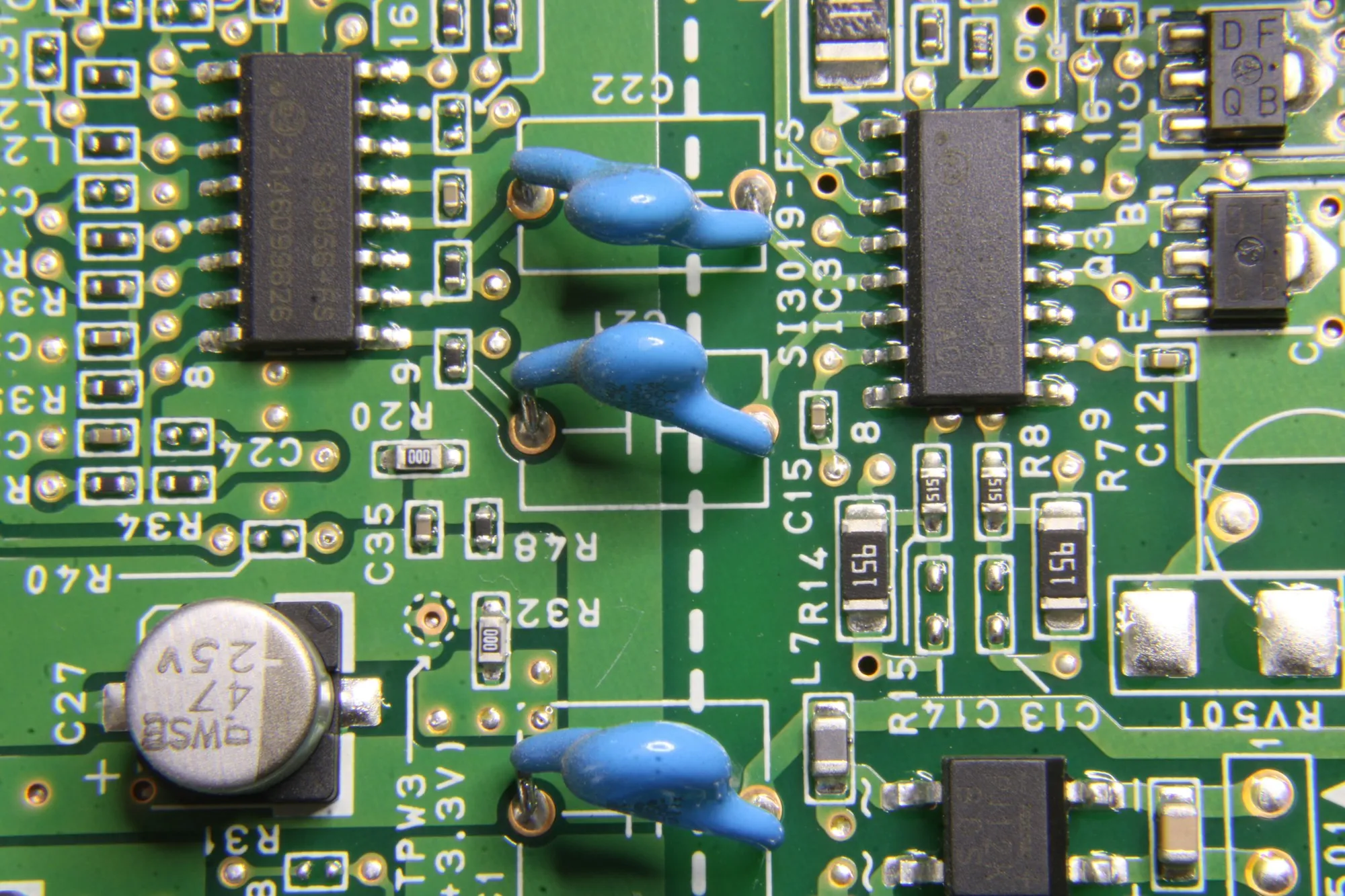
Receiving-side control hardware for LED modules, commercial display units and custom display structures.
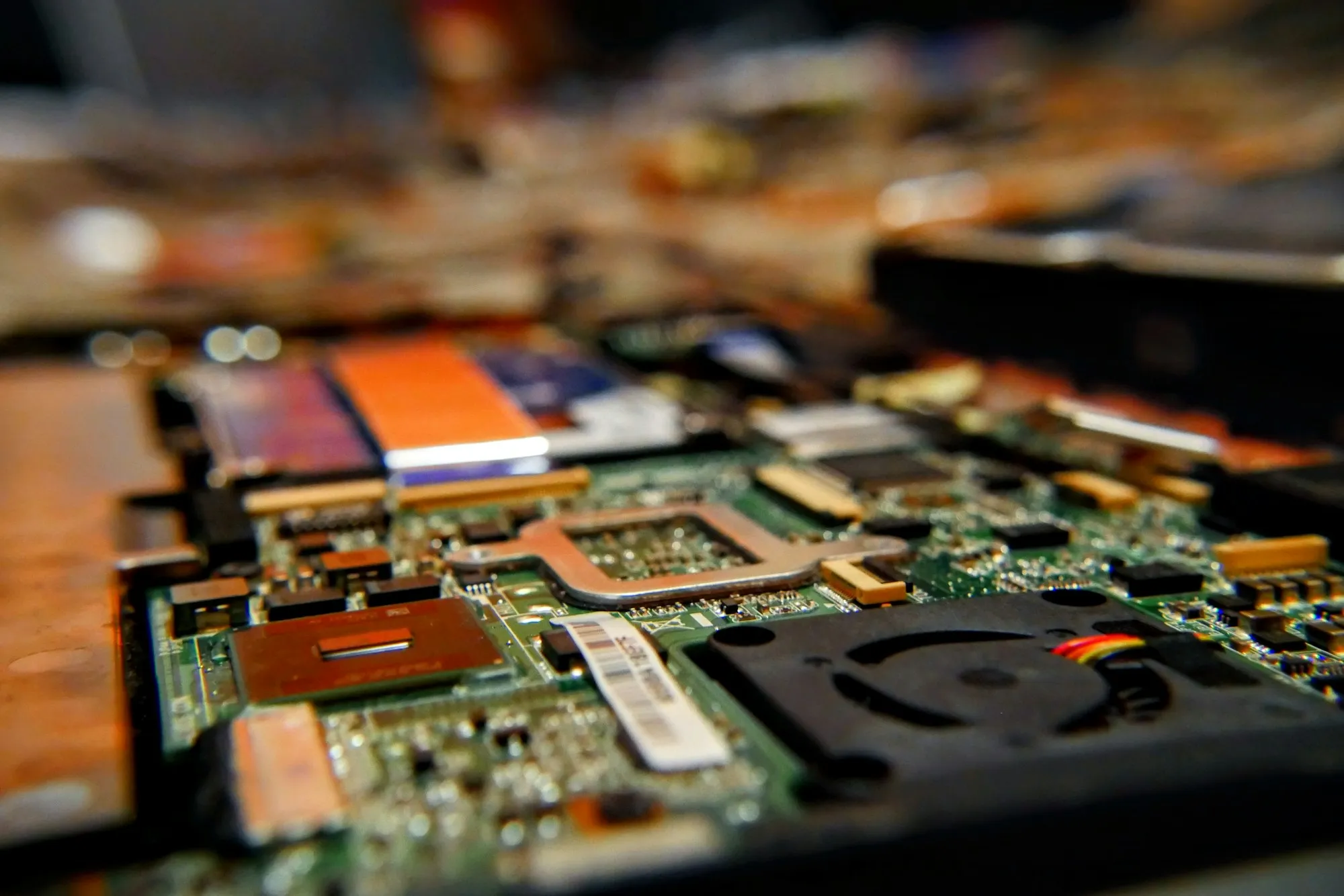
Integrable control boards, interface boards and modular hardware for advertising screens, small display products and custom devices.
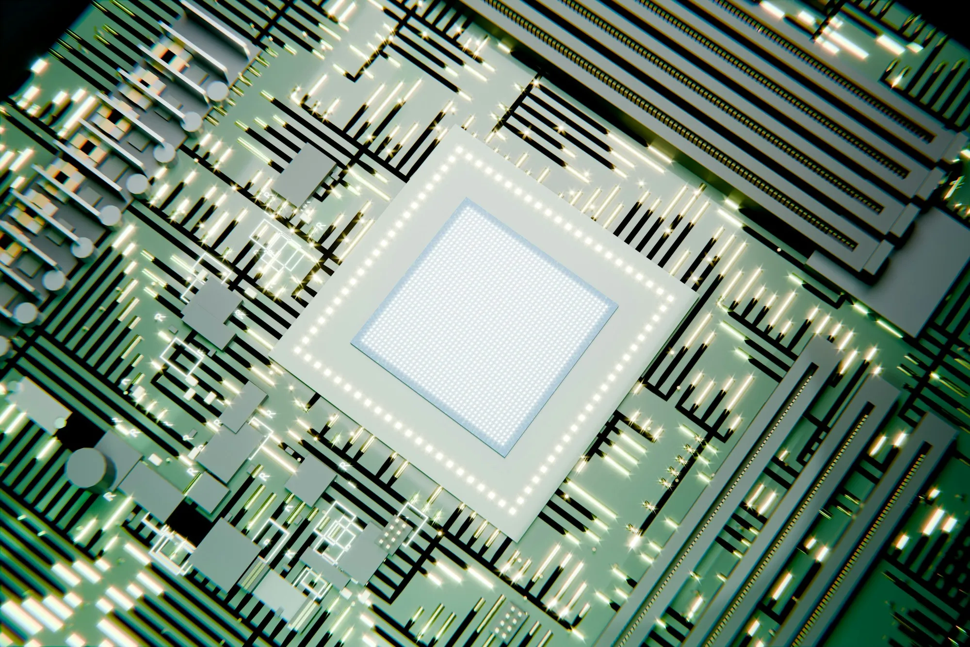
Adapter and interface boards that bridge an existing main controller, display module or harness to the rest of the control chain.
ODM PROCESS
Six stages
Each stage states what the customer supplies, what the work covers and what is delivered.
Clarify display type, application scenario, screen size or resolution, refresh needs, input/output interfaces, control method, installation environment, mechanical limits, target cost, planned quantity and project stage. The aim is not an immediate quote but turning a vague requirement into engineering questions that can be judged.
Break the requirement into source, control core, sending/output unit, transmission link, receiving/module control, display output, power, structure, firmware and production-test boundaries — and decide what the FPGA carries, what the MCU carries, and whether separate sending, receiving or interface boards are needed.
Develop schematic, PCB, key component selection, BOM, test points, interface definition and board-version management. PCB work accounts for high-speed signal integrity, power stability, thermal path, connector position, assembly, production test and later repair — designed for manufacture, not only for the lab.
Develop and debug FPGA control logic, MCU firmware, interface communication, power-on sequence, status feedback, exception handling and the debugging workflow — locating whether an issue sits at the input, the control logic, the transmission link, the receiving side, the module, power, mechanical interference or the firmware flow.
Validate power-on, communication, display output, interface link, timing, sync, stability, basic aging and issue reproduction. The point is not a single demonstration but confirming the approach is ready to be revised, piloted and integrated into the customer device.
Support component sourcing, alternative-part review, test fixtures, test workflow, acceptance criteria, batch records, packaging and supply-chain issue closure. The cooperation model, test scope and delivery boundary are confirmed per project rather than promised as a fixed lead time.
IN PRACTICE
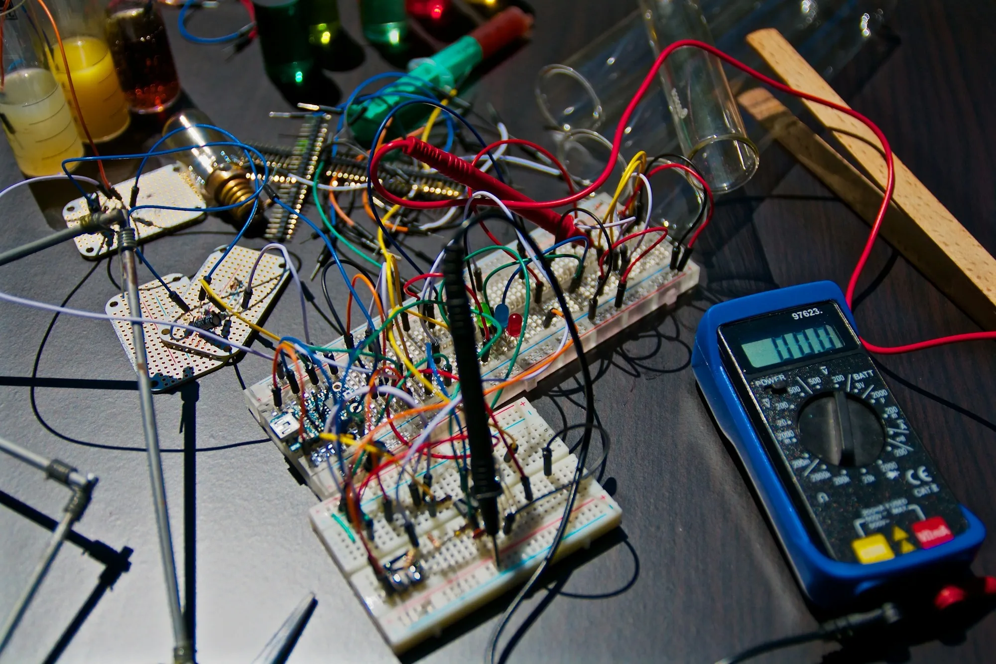
Prototype validation
A prototype that lights up only proves the chain connects. Temperature drift, power-cut recovery, content-specific anomalies, re-plugged interfaces and substituted component batches are the risks that have to surface before production.
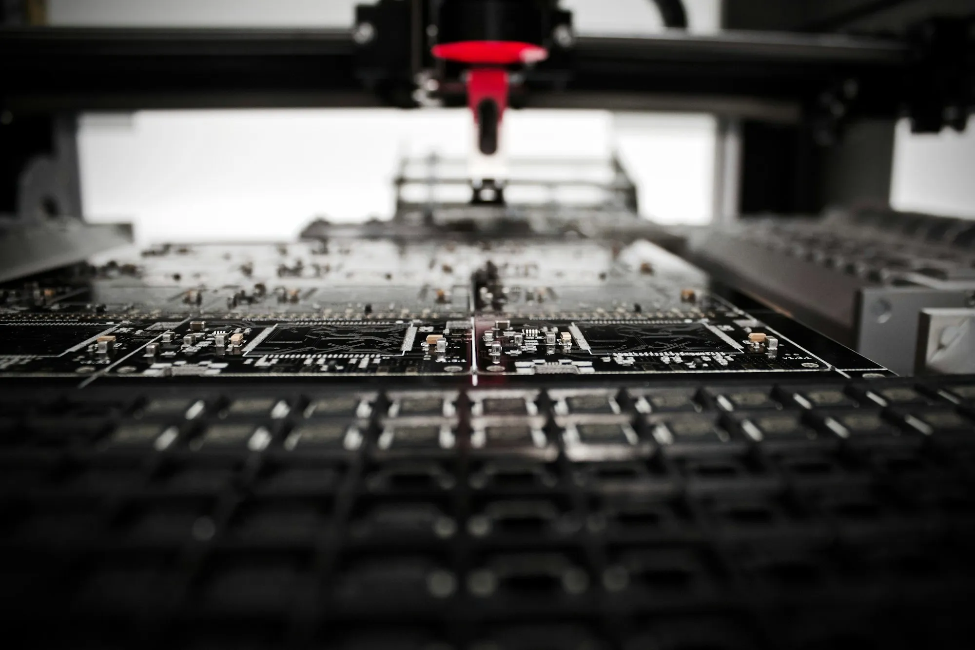
Production test
BOM, alternative parts, programming files, test workflow, test points, labelling rules and version records are considered during design, so a line can programme, test and judge by a fixed method.
Project inquiry
Share display type, target specifications, interface requirements and project stage. We review the control hardware approach and ODM cooperation model; pricing and lead time follow project review.
Helpful to include