Skip to content
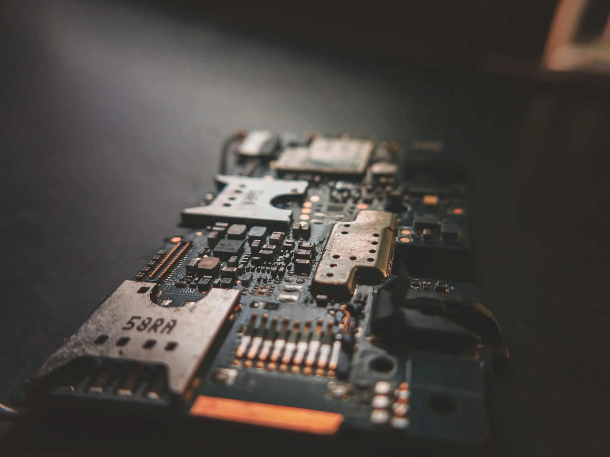
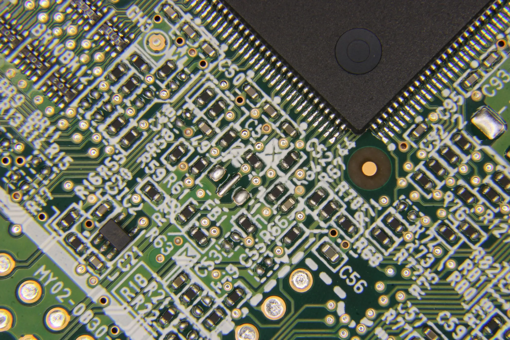
Macro detail of a black control board

Display control technology

Making display control a hardware system you can verify

Technical capability is not a list of board names. It is an engineering path built around FPGA, MCU, sending and receiving links, display timing, command protocol, prototype validation and production test.

Real-time layer
FPGA
Control layer
MCU command protocol
Verification layer
Prototype / pilot / production test

CONTROL CHAIN

Architecture mapping

System architecture from input to display

Breaking the requirement into source, control core, transmission link, receiving side, modules and device structure is what makes selection and customisation defensible.

  1. 01 Signal Input
  2. 02 FPGA / MCU Control
  3. 03 Sending / Output Unit
  4. 04 Transmission Link
  5. 05 Receiving / Module Control
  6. 06 Display Output
  7. 07 Production Test
HQControl works across the whole chain rather than a single board. The interface, timing and test boundary of each stage is defined during architecture.

ENGINEERING

Seven areas

Technical strengths organised as deliverable capability

Each area states the customer problem, the engineering action, the verification method and the deliverable — rather than adjectives such as “high-speed and stable”.

High-Speed FPGA Display Control Architecture

High-Speed FPGA Display Control Architecture

FPGA-centred handling of high-speed display links, timing control, pixel channels, interface conversion and complex display structures.

  • Define the FPGA control core, input/output links and board interfaces around the display product target.
  • Build hardware logic for high-speed data, pixel channels, timing control and interface conversion.
  • Suitable for sending-side control, receiving-side links, display-module control and custom display structures.
  • Confirm display output, link stability and manufacturability through prototype bring-up and validation.

FPGA architecture definitiondisplay timing and signal path controlhigh-speed interface planningboard-level implementationprototype bring-up and validation
MCU Device Control and Interface Management

MCU Device Control and Interface Management

MCU-based device-state control, peripheral coordination, communication interfaces, user operation and complete-device logic.

  • Covers keys, sensing, communication, power state, peripheral control and device-level coordination.
  • Combines with FPGA display links, sending cards, receiving cards and interface boards into a complete control unit.
  • Supports prototype debugging, firmware-level fault location, production-test entry and status feedback logic.
  • Suits advertising screens, commercial displays, small display products and custom devices.

embedded firmware coordinationinterface and peripheral controldevice-state managementproduction-test entry support

Sending Card and Receiving Card Signal-Chain Capability

Sending Card and Receiving Card Signal-Chain Capability

Organise sending cards, receiving cards and display control modules around input, processing, distribution, transmission and display-side control.

  • Sending cards, receiving cards and display control modules are defined inside the complete signal chain.
  • The requirement is broken down by input, processing, output, transmission, receiving and display side.
  • Control hardware can be defined around advertising screens, commercial displays, LED modules and custom devices.
  • Specification, loading, interface, refresh and sync figures are published only after project verification.

sending-side output controlreceiving-side module controlsignal routing and distributiondisplay output validationsupporting documents and test notes

System Architecture Mapping from Input to Display

System Architecture Mapping from Input to Display

Break the requirement into source, control core, transmission link, receiving side, modules and device structure so it becomes developable and verifiable.

  • The device requirement is separated into signal, control, transmission, receiving, display and test boundaries.
  • A system diagram shows which part of the control chain each board is responsible for.
  • The application scenario is worked back into a hardware architecture and board combination.
  • Test points and debug access are planned at architecture stage rather than added later.

requirement-to-architecture mappinginput/output interface planningsystem-level hardware decompositiontest boundary definition

Display Quality, Timing, Sync and Stability Validation

Display Quality, Timing, Sync and Stability Validation

Validation workflows around display output, refresh, latency, sync, interface stability, aging tests and batch consistency.

  • Engineering-sample validation and production-test validation are handled as separate layers.
  • Workflows cover display output, interface communication, timing, sync, aging and batch consistency.
  • Test records, issue lists and revision suggestions carry the engineering result.
  • Performance figures require engineering test data or customer approval before they are published.

prototype validationdisplay output checksinterface communication testsaging and reliability reviewproduction test recordsbatch consistency review

Custom Display Hardware ODM and Co-development

Custom Display Hardware ODM and Co-development

Join the customer project across product definition, hardware approach, prototype validation, BOM coordination and pilot-production testing.

  • ODM here means joint definition and engineering execution, not build-to-print assembly.
  • Scope runs from requirement review and hardware architecture to board development, prototype validation, BOM and production test.
  • Work can start from zero or from an existing customer design that needs interface adaptation, cost optimisation or a revision.
  • Project boundaries are stated plainly: what is developed here, what the customer supplies, what is still to be assessed.

co-developmentcustom hardware solutionprototype and pilot supportBOM and sourcing coordinationmanufacturing test cooperation

Specifications, Documentation and Handover Structure

Specifications, Documentation and Handover Structure

Turn technical capability into specifications, interface definitions, test records and handover documents a customer team can read, compare and archive.

  • Project material is organised as requirement, architecture, interface, BOM, test, pilot and handover notes.
  • Each stage states what was confirmed, what is still open and what changed since the last revision.
  • This reduces the communication cost around versions, testing, issue closure and production introduction.
  • Anything published externally requires customer authorisation and internal review.

requirement briefinterface definitionBOM versioningtest recordsproduction handoff notes

VALIDATION

Why validation matters more than first light

A first prototype that lights up only proves the basic chain is connected. It does not mean the product is ready for production. Real problems appear at the boundaries: temperature drift after long operation, state recovery after a power cut, flicker or misalignment on specific content, an anomaly after a connector is re-plugged, compatibility from a substituted component batch, intermittent faults the line test cannot catch.

Every project is therefore validated in layers: board level, power and clock, interface communication, display test patterns, customer content, temperature and long-run behaviour, abnormal recovery, and production test. Where a project needs sync, latency or colour behaviour, the matching test items are added and confirmed against the project specification.

  • 01

    Power-on and basic communication

    Check power sequencing, board state, basic communication, abnormal recovery and the debug entry point.

  • 02

    Input/output interface stability

    Check the customer-defined input/output interfaces, connectors, cabling, transmission stability and boundary conditions.

  • 03

    Display output and timing

    Check display output, timing, refresh, sync and display-side control behaviour. Exact figures are confirmed against the project specification.

  • 04

    Aging and reliability

    Build test records around running stability, temperature, voltage, abnormal states and long-duration operation.

  • 05

    BOM and alternative parts

    Assess key component supply, alternatives, lifecycle, batch consistency and cost impact.

  • 06

    Production test and batch consistency

    Support test points, fixtures, workflow, pass criteria, issue closure and production handover.

TOPICS

Verifiable items

Display result, production test, BOM and documentation

These topics decide whether a project reaches volume, and whether the customer can maintain and revise it afterwards.

01

Display output, greyscale and colour verification

Display quality is broken into verifiable items rather than headline figures: test patterns, greyscale transition, low-brightness behaviour, colour consistency and stable refresh.

Engineering checks

  • Test-pattern rendering and greyscale transition
  • Low-brightness behaviour and brightness steps
  • Customer content shown under the agreed acceptance standard
02

BOM and component sourcing

A control-hardware BOM is judged on supply lead time, alternatives, electrical margin, package, temperature range, assembly process and batch stability — not on function alone.

Engineering checks

  • Risk list for key chips, connectors, power devices and crystals
  • Alternative parts and lifecycle review
  • Impact of a substitution on test and assembly
03

Production test and version traceability

Production test enters the design early: test points and programming headers at PCB stage, test commands and version readout at firmware stage, pass/fail criteria and records at production stage.

Engineering checks

  • Test points, programming and debug headers
  • Test commands, version readout and error codes
  • Test pattern, pass criteria, labelling and records
04

Documentation and project handover

An ODM project does not end at a prototype. Requirement confirmation, architecture notes, schematic/PCB/BOM, interface definition, firmware version, test records and revision history are what let a customer keep maintaining and iterating the product.

Engineering checks

  • Interface definition and connector pinout notes
  • Firmware / logic version naming
  • Production notes and revision history

DOCUMENTATION

What gets delivered

Engineering documents organised by stage

Documents are organised and handed over per project stage. Whether anything is published, and how much, requires customer authorisation and internal review.

  • Requirement review Requirement brief Locks down objectives, display parameters, interfaces, structure, cost, schedule and risks before development starts, in a form engineering, purchasing and management can confirm together.
  • Architecture definition Control-chain architecture note Explains the relationship between input source, control processing, sending side, receiving side, display module, MCU management, test interface and service method.
  • Board development Hardware design package Schematic, PCB, BOM, key component notes, connector definition, test points and assembly notes.
  • Control logic Firmware and logic package MCU firmware version, FPGA logic version, programming files, interface protocol, test commands and version naming rules.
  • Prototype validation Prototype bring-up report Records power-on, programming, bring-up, communication, test patterns, temperature rise, recovery and issue closure — the basis for a pre-production decision.
  • Pilot production Pilot test plan Defines line programming, display test, interface test, labelling, records and reject criteria so an engineering prototype becomes a production item.
  • Lifecycle Design change log Records the reason, scope and confirmation of hardware, firmware, BOM, structure and test-process changes so later maintenance stays traceable.

BOUNDARIES

What we publish

No performance promise is published before engineering data exists

HDR, low latency, sync, colour behaviour, loading and refresh figures are discussed as project requirements and verification directions. They are not promised outside a specific panel, input source, control chain and test condition: assessed during architecture, tested on the prototype, confirmed by result.

  • Figures on this site describe capability direction. Resolution, refresh, greyscale, latency, bandwidth, interface count and loading capacity are defined per project and confirmed by prototype testing.
  • No customer names, case studies, awards, certifications, patents, production capacity or lead times are published unless they are verified and approved for publication.
  • HQControl works on display control hardware and ODM engineering. It is not an LED video processing platform, a virtual-production system, a cloud ecosystem or a subscription product.

Project inquiry

Turn display requirements into validated, manufacturable control hardware

Share display type, target specifications, interface requirements and project stage. We review the control hardware approach and ODM cooperation model; pricing and lead time follow project review.

Helpful to include

  • Screen size, pixel pitch, module layout and target resolution
  • Input source, control distance, sending/receiving count and cabling
  • Enclosure space, connector direction, power, temperature rise and service access
  • Test patterns, long-run checks, restart recovery and the factory-test standard
  • Existing boards, BOM, schematics or fault samples, if any
  • Estimated volume, project stage and target schedule